Daisy-Chain PCIe Power Cables on GPUs: A Safety-First Guide with be quiet! Examples
How Daisy-Chain PCIe Cables Actually Work
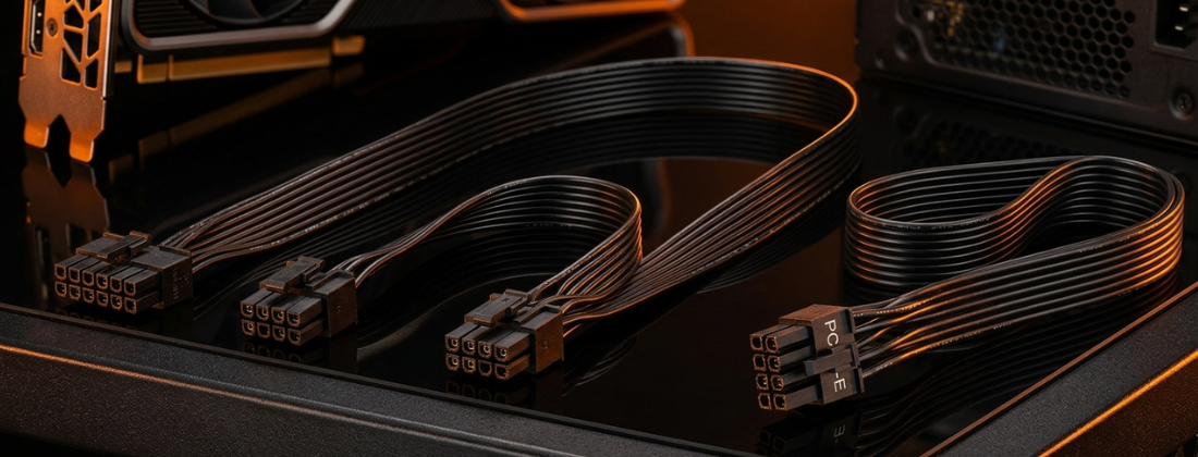
A daisy-chain GPU power cable is a single cable assembly that gives you two GPU-side PCIe plugs, usually 6+2 pin, from one PSU cable run. The GPU sees two connectors. The PSU sees one cable. That means part of the current path is shared between both plugs.
Where the current builds up
In a typical pigtail cable, the section closest to the PSU carries the combined current for both connectors downstream. Think of it like this:
[PSU] === (shared conductors) === [GPU plug A] === (branch) === [GPU plug B]
The shared segment carries roughly the sum of what both plugs are drawing. The branch to the second plug only carries that plug’s own current. This matters more than most builders realise, because resistive heating scales with the square of the current. Doubling the current through a segment roughly quadruples the heat generated there. If there is any weak point along that shared section, such as a poor crimp, a loose contact, or a tight bend, that is where heat will concentrate.
Connector standards and their rated limits
The connector standards set conservative but real limits. The PCIe auxiliary connectors are defined as follows:
- The 6-pin (2×3) connector is rated for 75 W.
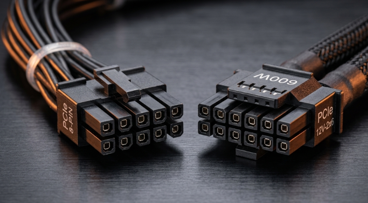
- The 8-pin (2×4, or 6+2) connector is rated for 150 W.
- The 12V-2×6 (16-pin) connector is designed for up to 600 W and includes sideband sense signalling to negotiate power and detect unsafe insertion.
If you feed two 8-pin GPU sockets from one pigtail cable, the shared upstream segment is effectively being asked to handle a 300 W class path. That is why best practice shifts toward separate cables as GPU power draw increases.
Pigtail vs Y-Split: Not All Two-Plug Cables Are the Same
Builders often lump all two-plug PCIe cable designs together. That is an oversimplification. There are two distinct topologies, and they behave differently under load.
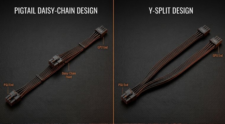
Pigtail (in-line daisy chain)
One connector sits partway along the cable run. The cable continues past it to a second connector further along. You will sometimes see this described with two distance measurements, such as 500/600 mm, meaning the first plug sits at 500 mm and the second at 600 mm. The upstream section from the PSU to that first plug carries the combined current for both connectors.
Y-split (two separate legs)
The cable splits near the PSU end into two separate legs, each running to its own GPU plug. Both plugs terminate at the ends of their respective legs rather than one being in-line with the other. The be quiet! CP-6620 accessory cable is described this way, with two separate PCIe 6+2 connectors and a single overall length measurement rather than staggered connector distances.
Why the distinction matters in practice
The table below summarises the key differences:
- Pigtail: The trunk section carries the combined current of both connectors. The first connector and the branch point are the most vulnerable spots under heavy load.
- Y-split: Each leg carries its own current after the split, which reduces the series loading on any single connector. However, the PSU-side port and internal rail limits still apply regardless of how the external split is arranged.
Neither topology creates extra PSU capacity. Changing the external split geometry only changes where heat and voltage drop are most likely to appear. If a PSU port, rail, or overcurrent protection setting is the limiting factor, that constraint remains.
Electrical and Thermal Safety: What Actually Causes Problems
Connector heating is often the limiting factor, not PSU wattage
Most builders focus on whether their PSU has enough total wattage. That is only part of the picture. High-current GPU paths are frequently limited by connector temperature rise and contact integrity rather than bulk PSU capacity. The 12V-2×6 design specification calls out 9.2 A per power pin position across 12 power contacts, with a 30 degree Celsius temperature rise limit and 16 AWG wiring required for all power and ground pins.
be quiet!’s own guidance on their 12VHPWR adapter cable warns against bending the cable within 40 mm of the plug and against horizontal bending near the connector. The reason is straightforward: stress on the cable near the plug can shift the contacts slightly, increasing resistance and therefore heat at that point.
Transient spikes can expose marginal cable choices
Modern GPUs do not draw a flat, steady current. They produce short-duration spikes that can run significantly higher than the average draw. The ATX 3.0 design specification formalises this with defined excursion ratios, including allowances for peaks up to three times the sustained limit for intervals of 100 microseconds or less. be quiet!’s own technical content on PCIe 5-era behaviour notes these same short-interval peaks and frames the risk as PSU overcurrent protection trips or voltage droop when the power delivery path was not designed with these excursions in mind.
A daisy-chain cable increases the current in the shared segment and reduces the headroom available before a weak contact, tight bend, or high-resistance crimp becomes a hot spot during one of these spikes.
Cable gauge and length add up quietly
Longer cables add resistance. Thinner conductors add more. be quiet!’s own accessory cable specifications give useful reference points here. Their single-connector PCIe cable (CP-6610) uses 16 AWG throughout. Their 12V-2×6 90-degree cable (BC073) also specifies 16 AWG for all power and ground pins. Where two-plug cables list both 16 AWG and 18 AWG, the 18 AWG sections are typically on the lower-current branches rather than the shared trunk.
One important reminder: modular PSU cable pinouts are not universally standardised across brands. Accessory cables should always be manufacturer-approved for your specific PSU series. A cable that physically fits a modular port is not necessarily electrically safe to use with it.
Three-Connector GPUs and Limited PSU Outputs
This is the situation where daisy-chain cables become most tempting. The GPU has three 8-pin sockets, but the PSU only exposes one or two PCIe cable outputs, or you only have two PCIe cable assemblies to hand.
Start with the GPU vendor’s instructions when a 16-pin adapter is involved
If your GPU uses a 12VHPWR or 12V-2×6 to multiple 8-pin adapter, treat that adapter as a load-sharing and safety-signalling device. It is not a free splitter.
The NVIDIA RTX 4090 Founders Edition quick-start guide is explicit: connect at least three independent dedicated cables with 8-pin PCIe plugs from the system power supply to the adapter. MSI’s installation warning for a one-to-four adapter goes further, showing four individual PCIe PSU cables and explicitly warning against close-to-plug bending. It also uses visible yellow pins as an indicator of incomplete insertion.
Using one pigtail cable to feed two inputs on a multi-pin adapter is precisely what these guides are warning against.
Safe options when the GPU uses three legacy 8-pin connectors
If your GPU genuinely requires three 6+2 or 8-pin plugs with no 16-pin socket, the practical hierarchy looks like this:
- PSU has three or more PCIe cable outputs: Use three separate cables, one per GPU socket. If your PSU is multi-rail, spread the cables across the recommended sockets.
- PSU has two PCIe outputs with two-plug cables: Use both cables. One cable covers two GPU sockets, the other covers the third. Where possible, prefer a Y-split style cable for the pair, and put the highest-draw GPU socket on a cable by itself if the card labels its sockets.
- PSU has only one PCIe output: Treat this as a PSU mismatch. Upgrading to a PSU with sufficient dedicated PCIe outputs, or one with a native 12V-2×6 path if your GPU supports it, is the right answer here. Forcing three GPU sockets onto one cable run, or using SATA or Molex to PCIe adapters, carries a real heating risk.
If you are shopping for a new PSU and your GPU has three 8-pin sockets, check the PSU’s cable count on the spec sheet before buying, not just the wattage rating.
be quiet! PSU Families and What They Offer for GPU Power
Without specifying a single PSU model, the most practical guidance is to choose a be quiet! family that either offers enough 6+2 connectors for your GPU’s needs or provides a native 12V-2×6 output so you can avoid multi-plug legacy wiring altogether.
Pure Power 13 M
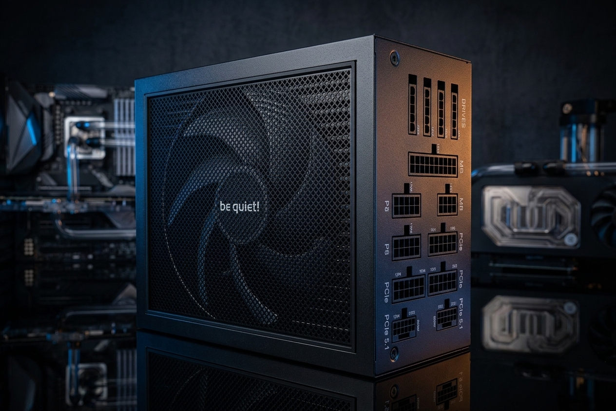
At 850 W, the Pure Power 13 M is positioned as an ATX 3.1 and PCIe 5.1-compatible unit with one PCIe 5.1 12V-2×6 600 W connector and four PCIe 6+2 connectors. It suits modern single-GPU builds that may run either a 16-pin GPU or a multi-8-pin GPU.
Dark Power 13
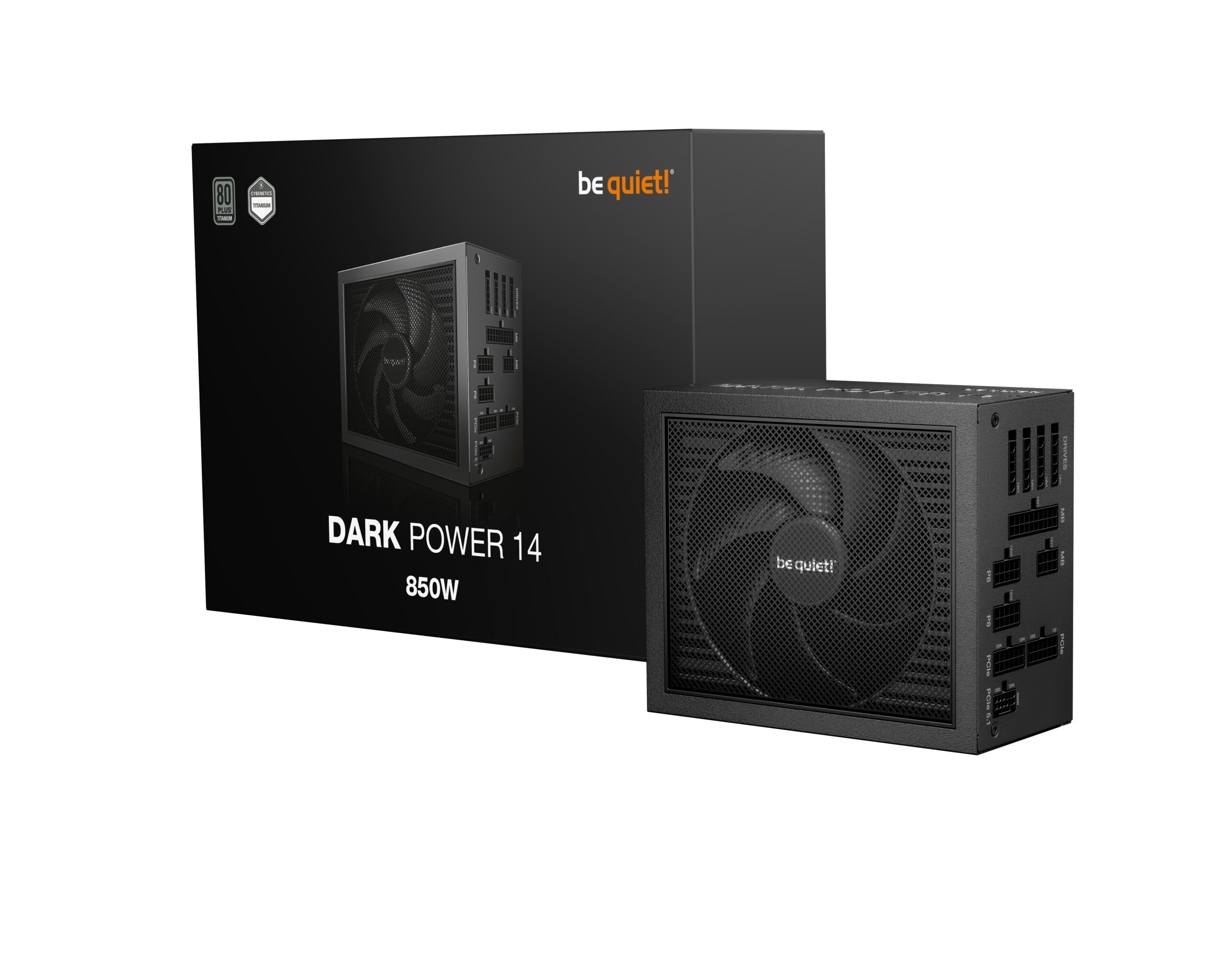
The Dark Power 13 is ATX 3.1 compliant and features a switchable overclocking key that lets you change between single-rail and multi-rail behaviour. That is useful in high-end builds where avoiding nuisance overcurrent protection trips matters, for example when the GPU produces large transient spikes on a single rail.
Dark Power Pro 13
At 1300 W, the Dark Power Pro 13 is built for power-dense systems. It provides two 12V-2×6 connectors and six PCIe 6+2 connectors, which gives genuine flexibility for workstation builds, very high-end single-GPU systems, or multi-GPU edge cases.
Earlier ATX 2.x be quiet! PSUs
If you are running an older be quiet! unit without a native 16-pin output, be quiet! sells a 600 W-rated 12VHPWR adapter cable that requires two PSU-side PCIe connectors and comes with specific bend and handling guidance. This is a legitimate option, but it means your safe cabling depends on having two free PCIe cable outputs on the PSU side, and you must follow the bend radius instructions closely.
12VHPWR vs 12V-2×6: What Changed and What It Means for Builders
The connector updates in the PCIe ecosystem are defined in the PCI Express Card Electromechanical specifications rather than the base protocol revisions. PCIe 5.0 introduced a new auxiliary power connector family supporting up to 600 W delivery, and PCIe 5.1 refined it. The 12V-2×6 connector defined in CEM 5.1 replaces 12VHPWR with specific improvements to reduce unsafe insertion scenarios.
What actually changed between 12VHPWR and 12V-2×6
The physical form is very similar, but the engineering changes are meaningful:
- Power pins are lengthened and sideband pins are shortened in the PCB header. This means power pins engage first and disengage last, reducing the chance that the sense signalling says the connection is fine while the power contacts are still marginal.
- Sense behaviour is tightened. When both sense lines are open, the updated design treats this as a zero-watt state, meaning a poorly seated or absent plug is explicitly treated as no power permitted rather than an ambiguous condition.
- The connector is keyed and marked differently (H++ versus H+) so you can distinguish 12V-2×6 hardware from 12VHPWR hardware.
Backwards compatibility in practice
There are two separate compatibility stories worth keeping clear in your mind.
For 6-pin versus 8-pin: the 8-pin header accepts a 6-pin plug for backward compatibility, with sense pins letting the card detect how much power it is permitted to draw. This is well-established and generally reliable.
For 12VHPWR versus 12V-2×6: the physical mating is broadly compatible, but compatibility still depends on correct insertion and correct sense-pin orientation. be quiet!’s 12V-2×6 90-degree cable explicitly warns that it may not work with all graphics cards unless the four sense lines are on the correct side, and it requires the connector to be firmly seated and flush before use.
On legacy 6+2 or 8-pin PCIe, the extra pins are not carrying more voltage. They provide additional return paths and sense signalling. On 12V-2×6, the four small sideband pins negotiate permitted power and communicate insertion status. Treating them as unimportant is the most common source of compatibility problems with high-power GPU cables.
Builder Checklist and Troubleshooting Common Problems
Step-by-step recommendations before you cable up
- Identify your GPU power interface. Three 8-pin sockets, two 8-pin sockets, or a single 12VHPWR or 12V-2×6 16-pin connector. If an adapter is involved, read the GPU manufacturer’s installation guide before touching a cable.
- Count your PSU’s actual available GPU cable outputs. Two modular PCIe ports with two-plug cables can provide four GPU plugs, but the conductors may be shared depending on the cable topology. Wattage rating alone tells you nothing about this.
- Prefer one PSU cable per GPU socket wherever your PSU supports it, especially on high-power cards or when using a 16-pin adapter.
- If you must use a daisy-chain pigtail, keep the shared segment cool and unstressed. Avoid tight cable bundling near it, avoid pressing the first connector sideways, and make sure there is reasonable airflow around that section of the cable run.
- For 12VHPWR or 12V-2×6 connectors, manage the bend radius as a first-class requirement. Keep at least 40 mm of straight cable run from the plug before any bend. If your case geometry makes this difficult, a purpose-built 90-degree cable such as be quiet!’s BC073 removes that constraint at the connector end, but you still need to ensure firm, flush seating and correct sense-pin orientation.
- Do not assume a PCIe 5.1 label means you can relax legacy best practice. High-power transient excursions exist in this ecosystem and can cause protection trips or instability when the power delivery path has any marginal element.
Troubleshooting symptoms
If your GPU power path is under-cabled or poorly seated, the failure modes tend to be repeatable rather than random:
- Instant shutdowns or black screens under load: Often indicates PSU overcurrent protection activating or voltage droop during a transient spike. More likely when multiple GPU sockets share one cable segment or one PSU rail.
- Melt smell, discolouration, or warmth near the plug housing: Stop immediately and inspect. This is nearly always a contact integrity problem caused by incomplete insertion or a stressed cable near the connector.
- GPU will not boot with a 16-pin cable or adapter: Can happen when sense signalling indicates insufficient permitted power, or when the connector is not seated fully enough for the sense pins to register correctly.
If you spot any discolouration on a PCIe connector or plug housing, do not reseat and carry on. Inspect both the cable and the GPU socket carefully. Heat damage at a connector is a sign of sustained high contact resistance, and the underlying cause needs to be fixed, not just the cable replaced.
Summary: When Daisy-Chain Cables Are Fine and When to Avoid Them
Daisy-chain PCIe power cables are not inherently dangerous. They are a practical solution in many builds, and PSU manufacturers including daisy-chain GPU power cable ship them as standard equipment. The risk comes from using them in situations they were not designed to handle.
Use a daisy-chain pigtail without much concern when the GPU is moderate power, when only one of the two connectors is actually drawing significant current, and when the cable is routed cleanly without tight bends or bundling near the shared segment.
Move to separate cables per socket when the GPU is high-power, when you are using a 16-pin adapter with a multi-8-pin input, and whenever the GPU vendor’s documentation explicitly says to. This is not an overcautious suggestion. The RTX 4090 Founders Edition guide and similar adapter documentation exist precisely because the consequences of getting it wrong scale with the amount of power involved.
If you are choosing a new PSU and want to avoid the question entirely for a modern high-end GPU, pick a unit with a native 12V-2×6 output and use the correct cable for it. The be quiet! Pure Power 13 M, Dark Power 13, and Dark Power Pro 13 all offer this alongside legacy 6+2 outputs for backwards compatibility.
The short version: match your cable topology to your GPU’s actual power requirements, follow the GPU vendor’s installation instructions for adapters, manage bend radius on 16-pin connectors, and do not confuse a PSU’s total wattage rating with the current-carrying capacity of a single shared cable segment.